I first need to determine what hardware components I will need. I will be using a Raspberry Pi to be the core of the Radio Alarm Clock. It will also mean that I can run any software I need. It comes with audio output, I2C, SPI and I2S buses and general purpose Input/Output pins. The I2C bus is very useful as it can connect lots of different devices on the same wires so you can daisy chain devices together and still control them as individual devices.
As I want Amazon Alexa to be a part of this I will need at least one microphone. I already have a ReSpeaker 4Mic array with an LED ring which can connect directly to the Raspberry Pi. The ReSpeaker 4Mic HAT also has a I2C Grove port and a Digital Grove Port. These ports simply pass through to the ports on the Raspberry PI.
The other components we need are a 7 Segment x 4 LED display to show the time, some way to handle touch sensors and a small amplifier with speakers to play the sound. Adafruit has a ton of great components with lots of specs and tutorials. I found a 4 Digit 7 Seg LED display with an I2C interface, a 2.8W amp with gain control over I2C, and a 8 input capacitive touch sensor with I2C interface. I also found a pair of speakers here
I will order the parts, and wait...
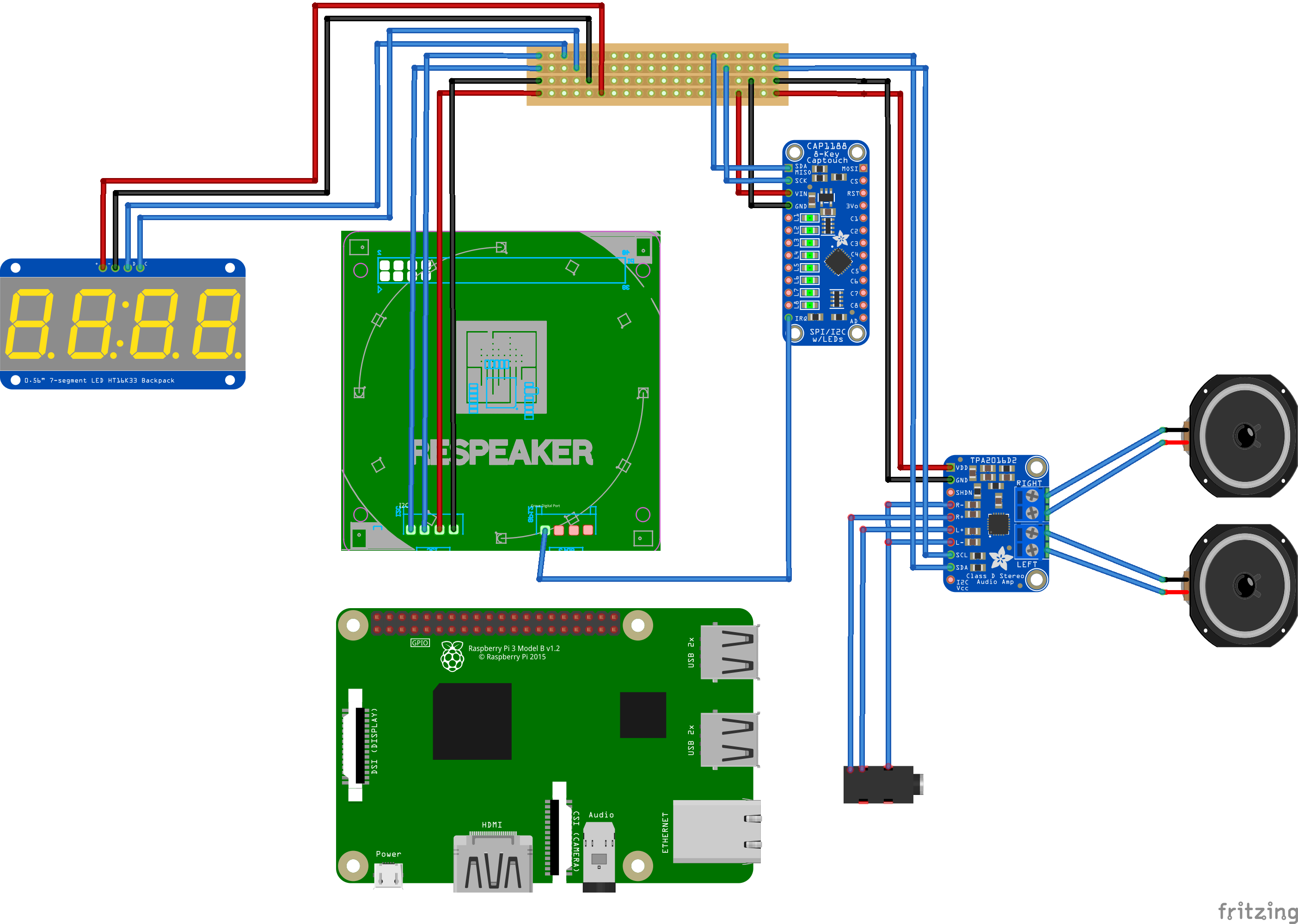
You can download the Frizting diagram here.
The design of the hardware looks like this:-